Hi!
Here, I post updates on my synthesizer development every once in a while. Have a look! I don’t do direct technical descriptions over here, that’s for separate blog-posts in the future.
2026-05: Acquire BNC cable & adapters to make use of the frequency generator #


2026-04: Abusing my step sequencer as a Midi-Controlled voltage reference #
- A Python Script on my computer:
- Reads a Midi file
- Extracts one voice
- Sends Midi Commands to the Beatstep Pro connected over USB
- The Beatstep Pro
- Receives the Midi Commands
- Directly converts the Midi Commands over to an analog 1V/Oct voltage reference
- The voltage reference is put into my synth VCO
- My synth VCO
- receives the voltage reference
- Generates a sound signal with an according frequency
Plus some extra effects!
2026-04: Acquire my own oscilloscope #


2026-02: Setting up an automated SPICE simulation using KiCad and PySpice to understand the VCF schematic #


2026-01: Visit Look Mum No Computer Concert, again! #

2025-11: Acquired new lab devices from employer #
- Fluke 81 Function Generator
- TTi EL302RT Triple Power Supply
2025-08: First proper jam on the modular synth! #
I extended my physical, analog synth with some VCV Rack modules to add the beat and some reverb effects.
2025-08: Buy VCF PCBs from Look Mum No Computer as a reference for my filter design #


I needed to cut of the top of the yellow PCB so that the module fits inside my case! I also therefore cut some traces, which I reconnected afterwards using wires. It’s pretty tight though!
2025-08: Design some utility modules #
Simple mixer (without voltage control of the volume)
- 4 sound inputs with potentiometers volume control
- 1 sound output
- not yet manufactured & built

Simple math module
- Functions
- Invert sound
- remove offset voltage
- add offset
- attenuate / amplify (using potentiometer as control)
- not yet manufactured

2025-05: Try to understand VCF (state variable) #
- First design on breadboard works, based on LM13700 Operational Transconductance Amplifier, but I want to make sure it works in every situation and the output is in voltage bounds
- current challenge: Linear to exponential converter
- if understood, the VCA module is also unlocked for design!
- I automated the SPICE simulation with python to find variation of cutoff frequency due to input voltage changes

- trying to understand state variable filter from music from outer space:


2025-05: Trying some Class-AB amplifier architectures from The Art of Electronics book #


2025-01: Design audio output module #
- It buffers synth audio signals and attenuates them significantly to line level and use NE5532 OpAmps for headphone output
- can switch between mono & stereo!

(I don’t have videos testing the output module individually, but some related here)
2024-12: Build a CLI to search in my part inventory #
- I ordered too many parts and unfortunately cannot remember all the component IDs! TL072 for my OpAmps is easy, but MCP3008 for an 8 channel ADC is not!
- You find it here: https://github.com/NEOZEO64/InventoryTool
- basically, it is only a json parser with some array filtering mechanics

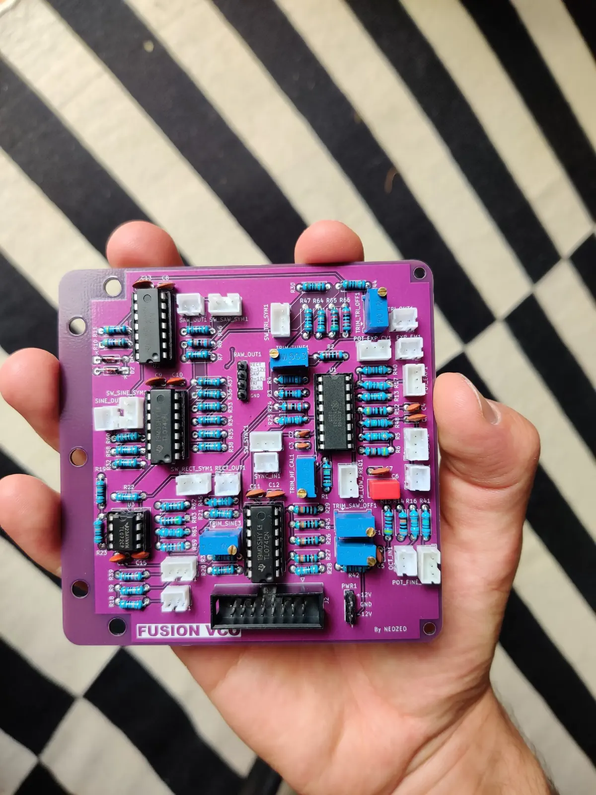
2024-09: Soldering finished VCO PCBs #


2024-08: Design proper working, functional VCO #


2024-08: Hack AAAPPPCCC from Look Mum No Computer into my synth #
(easy one-day project)
- measured dimensions
- designed some laser cutter guide
- laser cut at the student research center
- sprayed black and drew fancy UI
- soldered on adapter connectors (fortunately the AAAPPPCCC module needs 12VDC for power that can be easily provided from the eurorack plugs, also the audio signal levels are fine)
- done


2024-08: Build decoration module #
- It was necessary to put my name tag on the synth xD
- But with RGB leds!
- Used a Raspberry Pi Pico, powered by the 5V line on the eurorack plug
- Used WS2812B RGB leds
- Soldered a simple PCB and wrote a small MicroPython firmware for the Pico to control the LEDs


2024-08: PSU PSBs arrived! Solder and test… #


2024-07: Meet with friend to build the case #
- Wooden box sprayed black
- 1 m wide from the inside, 20 cm deep, 20 cm height from the inside
- materials bought from Bauhaus Germany, for around €55
- used 2x Adam Hall 6161 as cheap rails

2024-07: Visit the Thomann music store in Bavaria, Germany #

2024-07: Design proper PSU PCB without the anxiety of shorts because of bad soldering #
- similar circuitry like the prototype power supply
- it has a lot of proper 16 pin eurorack connectors
- it has fuses, a prototype area and debug headers
- contains very ugly mistake: The main power PCB traces are a little thin


-
Why not choose the RT65W? It got plenty of power! Because I heard it is noisy, and the voltage rails have not equal power
-
Why not choose prefabricated linear regulator power supply? (e.g. https://frequencycentral.co.uk/product/microbus/?attribute_pa_purchasing=pcbs-only) Because it’s a little expensive and I want the challenge
-
Why not choose all in one power supply with easy DC wall wart? (e.g. https://www.mouser.de/ProductDetail/TDK-Lambda/CCG30-24-12D?qs=Cb2nCFKsA8qvzo4xGj%"252BciQ%"3D%"3D) …it is expensive
Next challenges
- Make PCB trace width bigger
- Connect all Gate / CV Eurorack ports
2024-06: Design first revision of VCO (and do first PCB designing experience) #
-
Build and validate the circuitry found on the internet

Figure 42: Testing the VCO on breadboard -
Design first revision & meet with friend to solder it

Figure 43: Test first revision of VCO PCB - had some faults and wrong footprints, I wasn’t happy
- also, the holes at the corners were a lot too small to mount it anywhere
-
Design & 3D-print the front panel (with a height of 16 cm)

Figure 44: 3D-Print the front panel, put UI elements in and connect PCB to it -
Set up prototype test rail from toy metal kit
Video 9: Complete setup inside test rail, applying reverb effect on the sound
2024-05: Gather more lab devices! #
(frequency generator & oscilloscope are borrowed from student research center)

2024-04: Go to Look Mum No Computer Concert in Hamburg! #

2024-03: Plan the case #
Draw some fancy ideas!


Buy more parts!

2024-02: Playing with circuits (voltage controlled oscillators and filters) #
- I built some simple VCOs (voltage controlled oscillators)
- I built a simple VCF (voltage controlled filter)
- Made a lot of plans
- I chose the Cosmo standard from Look Mum No Computer for dimensions and electronic properties of signals etc.
- could not decide on whether the module height of 16 cm or 20 cm is better. 16 cm seemed more handy, but 20 cm are definitely a good decision! You have so much space and the synth takes in the room it deserves!


I also tested some counter IC

2024-02: Build a prototype of a bipolar ±12V power supply #

I didn’t want to use dual 9V block batteries, for a ±9V power supply, so built a wall wart power supply: How does it work?
- A 14V AC voltage is fed into this power supply from an external transformer (from Roland, bought from Thomann)
- A half bridge rectifier + 6x 4700uF capacitors are used to generate a bipolar, but unstable voltages (If I remember around 20V if unloaded)
- For +12V and +5V, step down converters are used (LM2596S) to avoid linear voltage regulators that heat up
- For -12V, the L7912 linear voltage regulator is used, as I did not see another easy way
2024-02: Buy, buy, buy! #
To get started, I needed a lot of materials and books:
- E-Books from Make
- The Art of Electronics
And a lot of different electronic parts:
- Mouser, Reichelt
- Aliexpress
- Thomann
- ElectricDruid (for old analog chips)
The first order cost me around €700 in sum, I felt reallly excited, but also under pressure, whether my plan goes well.

2023-11: Trying out modular synths in real life #
Hamburg’s Elbphilharmonie offers a modular synth course every once in a while. I took part, it was fun to turn the knobs in real life and play together with other people!
