Hi!
In the Smart Sensors university course, a colleague and I had the task “Develop a gesture based game controller to play a racing game”! Now you can say that’s easy: Just connect an arduino with accelerometer to the pc, and let the arduino emulate the keyboard. Noo! In our course, we dealt with so called Field-Programmable Gate Arrays, or in short FPGAs.
FPGAs?? #
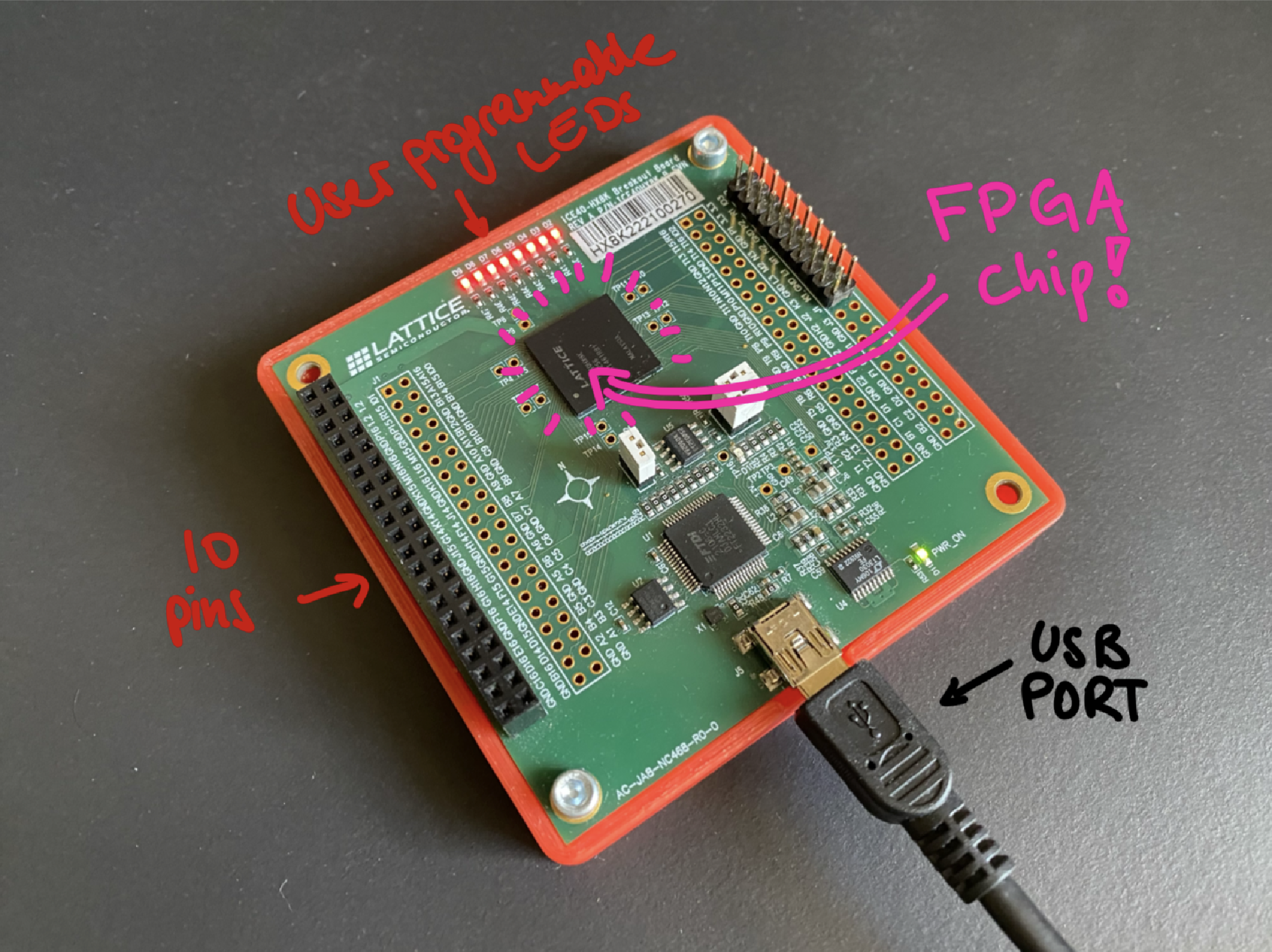
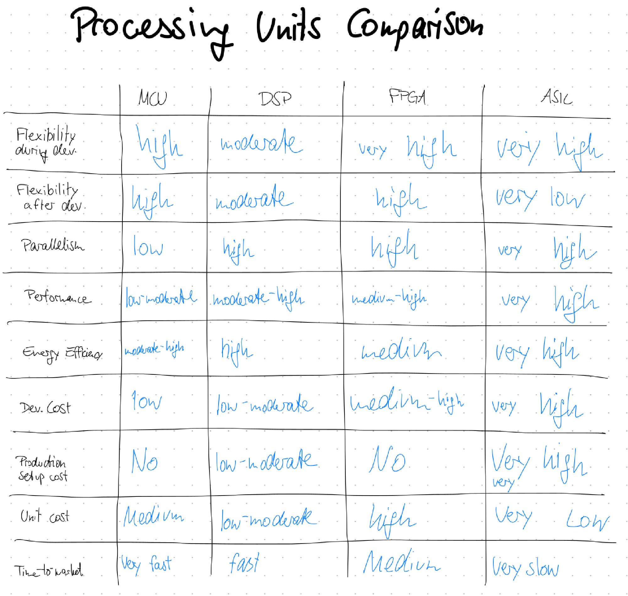
These are complicated, but pretty cool computer chips that can emulate any computer hardware you want! With a small, low-cost one, you can implement IoT devices with extremely low power consumption. With a little bigger one, you can emulate old game consoles by simulating the real hardware. And with huge, high-cost FPGAs, you can simulate whole CPUs, which helps to validate your chip designs before starting the million-dollar chip-manufacturing. The first attachment shows an extensive comparison between the different computing units.
Pros and Cons of FPGAs #
FPGAs are cool because of their flexibility - they essentially are programmed by a hardware description language that defines exactly how circuits are set up internally. The FPGA code is like a file storing a Minecraft world only with redstone (although a little more efficient and hand-writeable!). There exist different hardware description languages, popular are Verilog (we learned that) and VHDL.
With their flexibility, FPGAs allow for extreme optimization of programs. Since everything can be defined from scratch, unnecessary overhead can be completely stripped out or custom hardware ideas can be introduced.
Also, everything runs in parallel! – Since an FPGA is essentially a big circuit.
These advantages also come with their downsides: It is pretty complicated to develop FPGA code. Debugging is also not that easy. In addition to that, FPGAs are not cheap like general purpose microcontrollers.
FPGAs! #
Our Smart Sensors challenge #
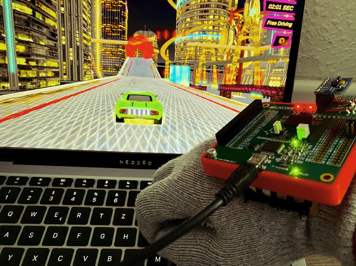
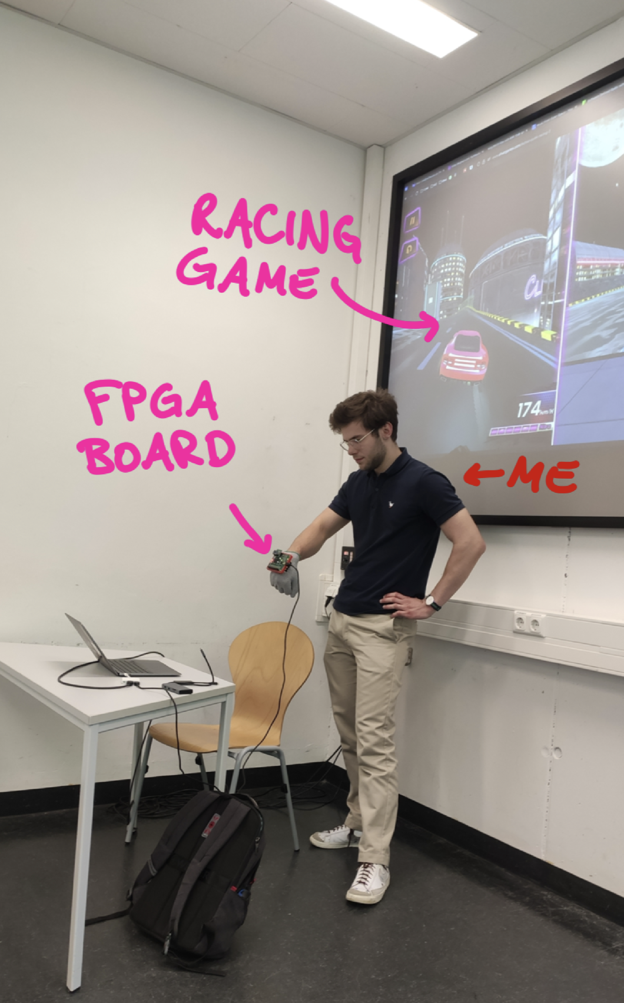
We were given the task to develop a controller for a racing game that depends on the gesture – in other terms, we were given our educational FPGA board, an accelerometer and that was it. (Of course we were given a lot of guidance on how to code using Verilog etc.)
The racing game that it’s about is the browser game: “Two Punk Racing”.
By reading out the accelerometers’ data, we could implement several actions:
- Accelerate by tilting hand forwards
- Steering by tilting hand left / right
- Braking / Driving backwards by tilting hand backwards
- Also a bonus gesture: Tapping onto the acceleration sensor enables temporary speed boost (“Nitro”).
Since the FPGA board can output data only using serial communication / UART, we set up the following data pipeline:
- FPGA sends characters using UART to the pc
- A python agent listens to the UART communication and emulates a keyboard by virtually pressing W/A/S/D keys (and N for nitro).
- The pressed keyboard keys control the game.
We documented our process a little in this presentation. You can find a verilog code snippet in the attachment 2.
Presentation
Summary #
Although getting into FPGAs was quite hard – developing the SPI and UART interface from scratch is definitely not easy – it was quite fun as it came together at the end! Also, by implementing the interfaces yourself, the understanding really improves. After the course, I wanted to play around with FPGAs some more, so I implemented a CPU interpreting the brainfuck programming language. Probably I’ll write an article in the future about it!
I am interested in your thoughts! - Reply with a simple Email
Have a nice day,
Carl
Attachments #
Attachment 1: Processing Unit Comparison #
- MCU: Microcontroller Unit (Like Arduino)
- DSP: Digital Signal Processor (can be found in audio gear, medical devices, etc.)
- FPGA: Field programmable gate array
- ASIC: Application specific IC (integrated circuit)
Attachment 2: Nitro Glove Verilog code sample #
module top(
    input wire hwclk,
    input wire spi1_miso,
    input wire adxl_int1,
    output wire ftdi_tx,
    output wire spi1_sclk,
    output wire spi1_mosi,
    output wire spi1_cs,
    output wire led0, led1, led2, led3, led4, led5, led6, led7
);

    // System clock frequency (predefined by hardware crystal)
    parameter CLK_FREQ = 12_000_000;

    // Duration of Nitro mode (2 seconds @ 12 MHz clock)
    parameter NITRO_TIMEOUT = CLK_FREQ/20;

    // SPI control signals
    reg [5:0] spi_address = 6'h00;
    reg spi_read_write = 1'b0;
    reg spi_start = 1'b0;
    wire spi_ready;
    reg [7:0] spi_data_in = 8'h00;
    wire [7:0] spi_data_out;

    ///////////////////////////////////////////////////////////////
    // DEFINE ACCELEROMETER SPI INTERFACE

    // Accelerometer raw and filtered axis values "variables"
    reg [15:0] x_axis, y_axis;
    reg signed [15:0] x_axis_filtered = 0;
    reg signed [15:0] y_axis_filtered = 0;
    reg [7:0] x0, x1, y0, y1;

    // Instantiate an SPI interface to communicate with ADXL345 (CPOL=1, CPHA=1)
    // Module is defined in another verilog file
    spi_module #(
        .CPOL(1), .CPHA(1), .SCK_DIVIDE(24),
        .CPU_CYCLES_BETWEEN_SPI_COMMUNICATIONS(2)
    ) spi_inst (
        .clk(hwclk),
        .start(spi_start),
        .ready(spi_ready),
        .read_write(spi_read_write),
        .address(spi_address),
        .data_in(spi_data_in),
        .data_out(spi_data_out),
        .spi_clk(spi1_sclk),
        .spi_mosi(spi1_mosi),
        .spi_miso(spi1_miso),
        .spi_cs(spi1_cs)
    );


    ///////////////////////////////////////////////////////////////
    // DEFINE UART / SERIAL COMMUNICATION TO USER COMPUTER

    wire uart_clk;
    reg uart_clk_prev = 0;
    reg [7:0] uart_buf = 8'h78;
    reg en = 0;
    wire uart_busy;

    // Divide 12MHZ hardware clock down to 9600 baud (needed for UART)
    clock_divider #(.DIVIDE_BY(1250)) uart_clk_gen (
        .clk_in(hwclk), .reset(1'b0), .clk_out(uart_clk)
    );

    // Instantiate UART configuration and transmission
    // Module is defined in another verilog file
    uart_tx_8n1 uart_tx_inst (
        .clk(uart_clk), .en(en), .Data(uart_buf), .busy(uart_busy), .uart_tx(ftdi_tx)
    );

    ///////////////////////////////////////////////////////////////
    // DEFINE FINITE STATE MACHINE (to have some kind of control flow and avoid everything being parallel)

    // FSM clock: 1Hz tick
    wire test_clk;
    reg test_clk_prev = 0;

    clock_divider #(.DIVIDE_BY(CLK_FREQ/60)) fsm_clk_gen (
        .clk_in(hwclk), .reset(1'b0), .clk_out(test_clk)
    );

    // FSM control variables
    reg [7:0] program_counter = 0;
    reg sensor_ready = 0;

    // Nitro mode trigger using ADXL345 INT1
    reg nitro_mode = 0;
    reg [25:0] nitro_counter = 0;
    reg adxl_int1_prev = 0;
    reg adxl_int1_rising = 0;

    ///////////////////////////////////////////////////////////////
    // Use accelerometers tap detection to enable turbo mode!

    // Detect rising edge on tap interrupt pin
    always @(posedge hwclk) begin
        adxl_int1_rising <= (~adxl_int1_prev) & adxl_int1;
        adxl_int1_prev <= adxl_int1;

        if (sensor_ready && adxl_int1_rising) begin
            nitro_mode <= 1;
            nitro_counter <= NITRO_TIMEOUT;
        end

        if (nitro_mode && nitro_counter > 0)
            nitro_counter <= nitro_counter - 1;
        else if (nitro_mode && nitro_counter == 0)
            nitro_mode <= 0;
    end


    ///////////////////////////////////////////////////////////////
    // IF GLOVE TILT DETECTED IN SPECIFIC DIRECTION,
    // THEN SEND CHARACTER OVER UART TO COMPUTER

    // Gesture recognition thresholds
    parameter signed [15:0] X_LEFT_THRESH  = -16'sd70;
    parameter signed [15:0] X_RIGHT_THRESH =  16'sd70;
    parameter signed [15:0] Y_FWD_THRESH   =  16'sd70;
    parameter signed [15:0] Y_BWD_THRESH   = -16'sd70;


    reg [7:0] gesture_char;
    always @(*) begin
        if (nitro_mode)
            gesture_char = 8'h6E; // 'n'
        else if (x_axis_filtered < X_LEFT_THRESH)
            gesture_char = 8'h6C; // 'l'
        else if (x_axis_filtered > X_RIGHT_THRESH)
            gesture_char = 8'h72; // 'r'
        else if (y_axis_filtered > Y_FWD_THRESH)
            gesture_char = 8'h66; // 'f'
        else if (y_axis_filtered < Y_BWD_THRESH)
            gesture_char = 8'h62; // 'b'
        else
            gesture_char = 8'h78; // 'x'
    end

    ///////////////////////////////////////////////////////////////
    // FSM logic
    always @(posedge hwclk) begin
        if (test_clk && !test_clk_prev && spi_ready) begin
            program_counter <= 0;
            test_clk_prev <= 1;

        end else if (!test_clk && test_clk_prev) begin
            test_clk_prev <= 0;

        end else if (program_counter == 0) begin
            // tap_threshold
            spi_address <= 6'h1D;
            //spi_data_in <= 8'h48; // Bigger tap threshold
            spi_data_in <= 8'h50; // Lower tap threshold
            spi_read_write <= 0;
            spi_start <= 1;
            program_counter <= 1;

        end else if (program_counter == 1) begin
            spi_start <= 0; program_counter <= 2;

        // ******************************************************
        // MORE FSM STATES IN BETWEEN: Read accelerometer X values using SPI
        // ******************************************************

        end else if (program_counter == 22 && spi_ready) begin
            x1 <= spi_data_out; x_axis <= {spi_data_out, x0};

            // Applying low pass filter ("exponential moving average filter")
            // This reduces noise in the accelerometer measurement data
            if (($signed({spi_data_out, x0}) - x_axis_filtered > 100) || (x_axis_filtered - $signed({spi_data_out, x0}) > 100))
                x_axis_filtered <= $signed({spi_data_out, x0});
            else
                x_axis_filtered <= x_axis_filtered + (($signed({spi_data_out, x0}) - x_axis_filtered) >>> 1);

        // ******************************************************
        // MORE FSM STATES IN BETWEEN: Read accelerometer Y values using SPI
        // Also apply filter on Y-values too
        // ********************************************

        end else if (program_counter == 27 && uart_clk && ~uart_clk_prev) begin
            if (!uart_busy && en)
                en <= 0;
        end

        uart_clk_prev <= uart_clk;
    end

    // LED debug indicators
    assign led0 = test_clk;
    assign led1 = spi_start;
    assign led2 = !spi_ready;
    assign led3 = uart_busy;
    assign led4 = sensor_ready;
    assign led5 = adxl_int1;
    assign led6 = adxl_int1_rising;
    assign led7 = nitro_mode;

endmodule